
This story is part two of MakerBot’s series of design studies, exploring iterative design and the relationship between designers and their tools.
You’ve probably taken something apart just to see how it works. Maybe you fixed it, maybe you marveled at the ingenuity of the design, but something about it was fascinating.
I had this experience recently with a micro drone. It flies surprisingly well, has a camera, and even some stabilization features. With my curiosity getting the better of me, I decided to take it apart and reverse engineer it to create my own 3D printed design.
Using the existing motors, battery, and electronic boards, here’s how I did it:
1. Dismantle and evaluate hardware components
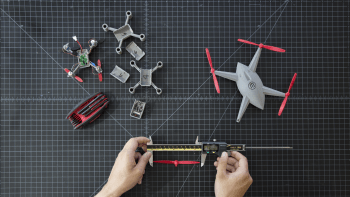
I began by disassembling the original drone carefully to expose the individual components and learn how they interact within the existing assembly design. Included in the assembly are a main board, a battery, an image board for the camera, and 4 motors for each of the four rotors.
Next, I considered what the constraints are going to be in my redesign; there’s a fixed distance between the motors, and the weight of my new design needs to be close to that of the existing design. I planned to maybe alter the location of the ports, the positioning of the boards, the wire routing, the overall structure, and further optimize for durability—because crashing drones is fun.

2. Create blind solids based on components
Using the basic information I had in front of me, I took measurements to design blind solids in CAD as placeholders for what the fixed constraints would be for a new, updated design. Calipers are a must for this. Try to get your dimensions down to at least 100 micrometers—especially at this scale.

3. Sketch new design variations, then input to CAD
With the existing components represented in CAD, I began sketching new variations of the crash-resistant design. Putting the blind solids in CAD helped to explore possibilities with an even better understanding of the spatial relationships.
Among other design decisions, I chose to change the arm structure to improve cable routing and add durability, while creating a more blocky, “kid friendly” hull.

4. Isolate new components and iterate individually
Body:
Working with a clamshell assembly, I took a shotgun approach and committed to testing five different fixture schemes. Using a 3D printer was a huge advantage here; these small bodies print incredibly fast on the Replicator+. It’s also important to keep the limitations of the printer in mind; which are particularly complex, tiny features.
Arms:
The main challenge here was cable routing. I tested a piping system for a cleaner look, however, it added too much additional weight to be feasible. Additionally, I tested trusses, which gave good strength and simplified cable routing.

5. Print preparation and 3D printing constraints
With a finished design mocked up in CAD, I imported the entire assembly into MakerBot Print to fine tune print settings. Mass economy is important, so I dropped the number of shells to 1, and the infill percentage to 3%. It took me a couple of tests to get down the perfect combination of shells and infill in order to keep the body light and the arms rigid enough to hold up the motor’s lift.
To ensure clean embossing on the low-relief logo on the top surface, I kept my text size larger than 8pt to avoid any spurring.

6. Print, test—repeat
With the prints finished, I labeled everything before taking them off the build plate to begin assembly and weighing. This is the stage where I learned the most; some parts didn’t fit perfectly; some arms were too heavy; some component layouts that made sense on the screen were obvious failures in the real world.
I took this batch of learnings and went back to iterating the individual components.

7. Fly the printed drone
Reverse engineering something is one of the best ways to learn how it works, while also sharpening other design and engineering skills in the process. You learn about the intentionality of design and manufacturing decisions and get to play a bit of forensics with why and how things are laid out the way they are. In this case, it was about hunting for opportunities for improvement, and the incremental improvements that define the iterative design process.
Now, lets fly this thing!